

Note that the MOSFET board requires 12V to turn on and so I used a simple voltage divider to drop the 24V down to 12V. The MOSFET board was connected directly to the power-supply and switched with the relay output of the temperature controller. Note that you can use a bi-metal switch as a method of temperature control on its own but that they tend to become stuck after a few thousand cycles.
#Cetus3d slicer full#
In series with the input to the heated bed was placed the bi-metal switch so that in the even that it becomes stuck on full power it should still stay within a safe temperature range. The resistors were wired up in a 4S-2P configuration so that the current draw from the power supply was around 4.2A for a total of 100W output. After many dozens of hours of printing this method appears to be working just fine. The power resistors were attached with two part epoxy as I did not have any thermal adhesive on hand.
#Cetus3d slicer upgrade#
Overall I would highly recommend this printer to anyone needing a cheap high quality 3D printer in a small form factor.Īfter seeing this video by Marco Reps I have decided to upgrade my printer to include a heated bed.
#Cetus3d slicer software#
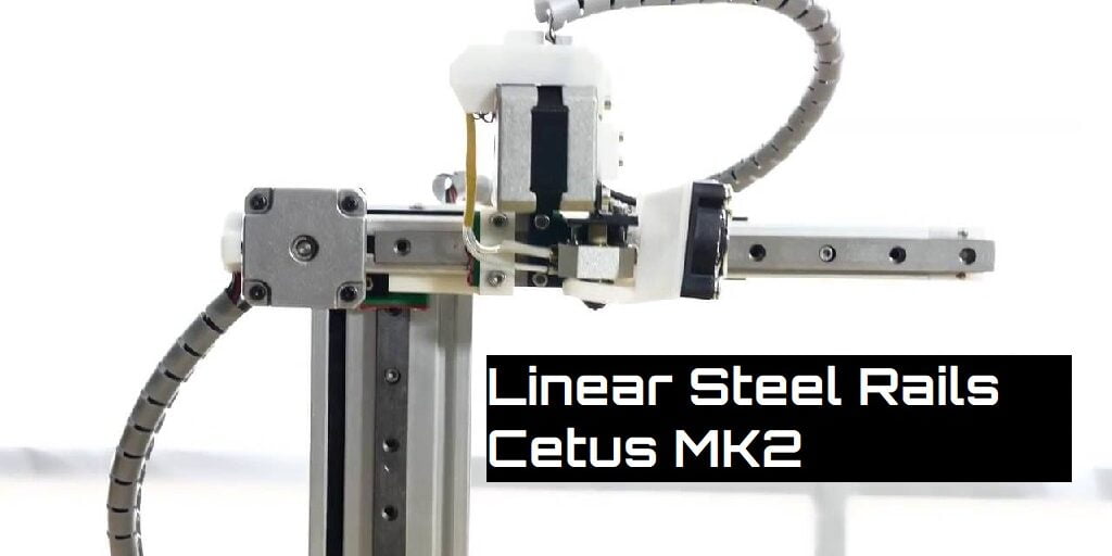
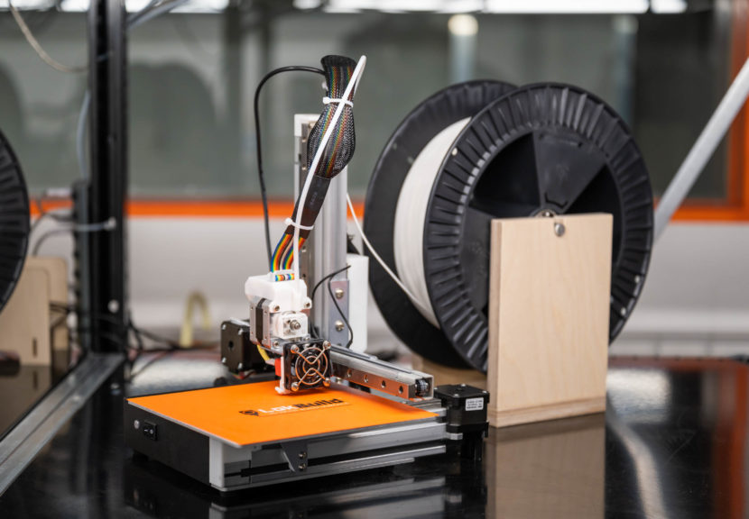
Included software has limited slicing options.Can print in Pet-G and ABS without a heated bed if you use a glue stick prior to the first layer.Can be modded for other uses such as a laser engraver.Extremely high print quality due to the use of linear rails and small nozzle sizes.So far I have been very happy with the results. A single seam is easier to treat as a post process and has less issue with stop start of the filament flow.Last year I purchased a Cetus 3D printer which I have now been using off and on for 8 months. This can contribute to small blobs on the print side as the flow is stopped and started in a new position. The seam you are seeing is the step to the next layer, usually there is an option to have random starts for new layers to try and hide the seam. I print about 20 or so of my calibration cubes per machine during a tune up. Hence my calibration cubes are printed direct onto 3M tape directly on the bed. What was the Z dimension on this two parts you made, are they identical ? Bit hard to measure as the raft can contribute to Z error. 1cm squares 5mm tall in different locations, map them and mark them before removing from the bed for comparison. If it is that, then it maybe a limit you are stuck with. Possibly a little spring in the table at that point that just adds a little squeeze to each layer printed. Slight difference in belt pitch or a pulley slightly off centre. The width difference could be put down to a combination of mechanical things working against you in that area.

Well the prints are pretty close to the ± 0.1mm tolerance.


 0 kommentar(er)
